FIRST
CHOOSE BETWEEN THESE OPTIONS THEN START TO READ THE ARTICLE, WE EXPLAINED ABOUT
DEVELOPMENT LENGTH
WHAT IS DEVELOPMENT LENGTH?
It is Used at
BEAM-COLUMN JOINT
OR
COLUMN-FOOTING JOINT.
To develop a safe bond between the bar surface & the concrete so
that no failure due to slippage of bar occurs during the ultimate load
conditions.
Also, the extra length of the bar provided as development length is
responsible for transferring the stresses developed in any section to the
adjoining sections (such as at column beam junction the extra length of bars
provided from beam to column).
GUIDELINES FOR DEVELOPMENT
LENGTH DESIGN | REQUIREMENTS FOR DEVELOPMENT LENGTH DESIGN | LCETED
DEVELOP
LENGTH CALCULATIONS
For
+ve moment, 𝐿𝑑 =
47𝜙 (for M 20 and Fe
415)
For
+ve moment, 𝐿𝑑 =
57𝜙 (for M 20 and Fe
500)
For
– ve moment, 𝐿𝑑 = 𝐿/4
At least 1/3 of the +ve moment steel in S.S. beam and 1/4
of the +ve moment steel in continuous beam extends to support for a distance of
𝐿𝑑/3
If
total bars = 6, therefore 1/3 × 6 ≥ 2 (means 2 bars will
curtail and 4 go to support)
For a cantilever beam, available development length is nearly
equal to span length
For
continuous beam, available length = 𝑥𝑜 + D
or 12𝜙 or 𝐿/16 (whichever is
greater); 𝑥𝑜 =
length of –ve moment region, i.e., the distance between the point of contra flexure
from the centre of support.
In practice, usually, bars are provided for a length = 𝐿/4 from the centre of
support which then becomes the available length.
At least 1/3 of the -ve steel should have an embedment
length beyond the point of inflexion not less than
D or 12𝜙 or
𝐿/16 (whichever is
greater)
Top steel in beams is to be spliced at mid-span (for 𝐿𝑑)
and bottom bars to be spliced near support after (2𝐷 𝑜𝑟 𝐿/4).
Lap of bottom steel in slab is to be done near support
(if required)
At the junction of beam/shear wall, 𝐿𝑑 =
1.5𝐿𝑑
If bars are provided in 2 layers, it is better to
curtail bars of layer 2 only.
For beams of up to 2.5 m, no need of curtailment of top
and bottom bars, i.e., all bars are ALTH (all through).
Curtailment:
TPC from centre of support,
𝑁′=no
of bars to be curtailed
𝑁𝑚𝑎𝑥 =
no of bars at mid-span
The actual point of cut off (APC) from the centre of support= 𝑥1 − 𝑒𝑓𝑓 𝑑𝑒𝑝𝑡ℎ(𝑑)
CALCULATION OF
DEVELOPMENT LENGTH
As per the Indian Standard – IS 456: 2000, clause 26.2.1 the
development length Ld is given the following expression;
Where,
Ø = nominal dia of reinforcement bar
σs = Stress in the bar at the section considered at design load
τbd
= Design bond stress
The formula given above is used to calculate
the required development length in mm for any bar dia, the same formula is used
for the limit state mode and the working pressure system. The only change in
the calculation in both methods is due to the different value of the design
bond stress; The values of the design bond for the limit level and working
pressure are as follows;
|
DESIGN BOND STRESS IN LIMIT STATE METHOD |
||||||
|
Concrete Grade |
M20 |
M25 |
M30 |
M35 |
M40
& Above |
|
|
Design Bond Stress (τbd, N/mm2) |
1.2 |
1.4 |
1.5 |
1.7 |
1.9 |
For
Plain Bars in Tension |
|
1.92 |
2.24 |
2.4 |
2.72 |
3.04 |
For
deformed bars in tension |
|
**Note: For bars in compression 1.25 times the above-given values shall
be used.
|
DESIGN BOND STRESS
IN WORKING STRESS METHOD |
||||||||
|
Concrete Grade |
M20 |
M25 |
M30 |
M35 |
M40 |
M45 |
M50 |
|
|
Design Bond Stress (τbd, N/mm2) |
0.8 |
0.9 |
1.0 |
1.1 |
1.2 |
1.3 |
1.4 |
For Plain Bars in Tension |
|
1.28 |
1.44 |
1.6 |
1.76 |
1.92 |
2.08 |
2.24 |
For deformed bars in tension |
|
**Note: For bars in compression 1.25 times the
above given values shall be used.
How to calculate the development length for different grades of concrete as per IS 456?
Example - 1
Given data
Calculate the development length for rebar in tension, by limit state
method for the below-given data.
Grade of concrete = M25
Reinforcement bar = Fe500 (σs = 500 )
Diameter of bar = 20mm. (∅ )
The development length Ld = ∅ × σs ÷ 4 ×
τbd
Ld = 20 × 500 ÷ 4 × 2.24
(τbd = 2.24 N/mm2 for M25 in tension, for the limit state. From the
above-given table,)
= 10000 ÷ 8.96
Ld = 1116.07mm.
Example - 2:
Given
data
Calculate the development length for rebar in
compression, by working stress method for the below-given data.
Grade of concrete = M30
Reinforcement bar = Fe415 (σs = 415 )
Diameter of bar = 16mm. (∅ )
The development length Ld = ∅ × σs ÷ 4 × τbd
Ld = 16 × 415 ÷ 4 × 1.6
(τbd = 1.6 N/mm2 for M25 in compression, for
the working stress method. From the above-given table,)
= 6640 ÷ 6.4
Ld = 1037.5mm.
As per thumb rule development length is 45d-55d.normally we take 50d.which means
for 16 mm dia bar development length would be 50*16 = 800mm=2.6 feet
FAQ ON DEVELOPMENT LENGTH
What
will happen if we don't provide development length?
REASONS
FOR PROVIDING DEVELOPMENT LENGTH
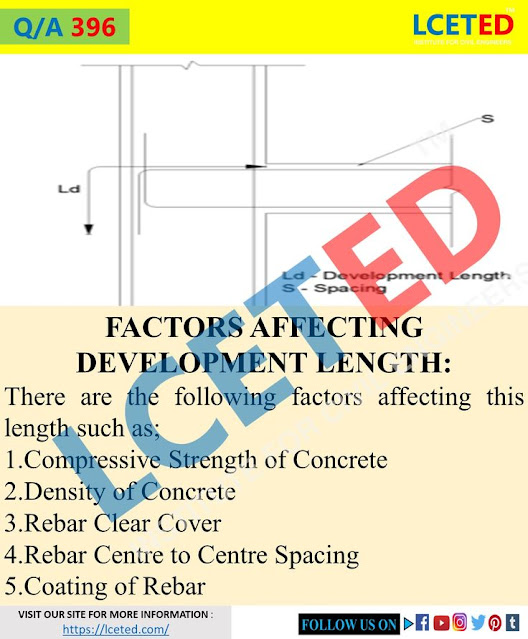
FACTORS AFFECTING DEVELOPMENT LENGTH?
What
will happen if we don't provide development length?
If you find
This information helpful, please share it.
Thanks! For reading the article.


No comments:
Post a Comment