Testing and Commissioning in UPS, Iso Trx, Battery Package| UPS, Iso Trx, Battery Package Factory Acceptance testing (FAT) | UPS, Iso Trx, Battery Package Site Acceptance testing (SAT) | UPS, Iso Trx, Battery Package Test Reports in Excel Sheet | UPS, Iso Trx, Battery Package List of Tests | UPS, Iso Trx, Battery Package Testing and Commissioning Requirement Compliance Sheet | UPS, Iso Trx, Battery Package List of Tests
In this article, we have listed out Types of UPS, Iso Trx, Battery Package Testing and Commissioning on factories and Sites for construction works, and Test Instrumentation Required/Considered for Site Acceptance Testing (SAT)
Following is the UPS, Iso Trx, and Battery
Package that shall be conducted in construction works
TYPES OF TESTING AND COMMISSIONING ON UPS
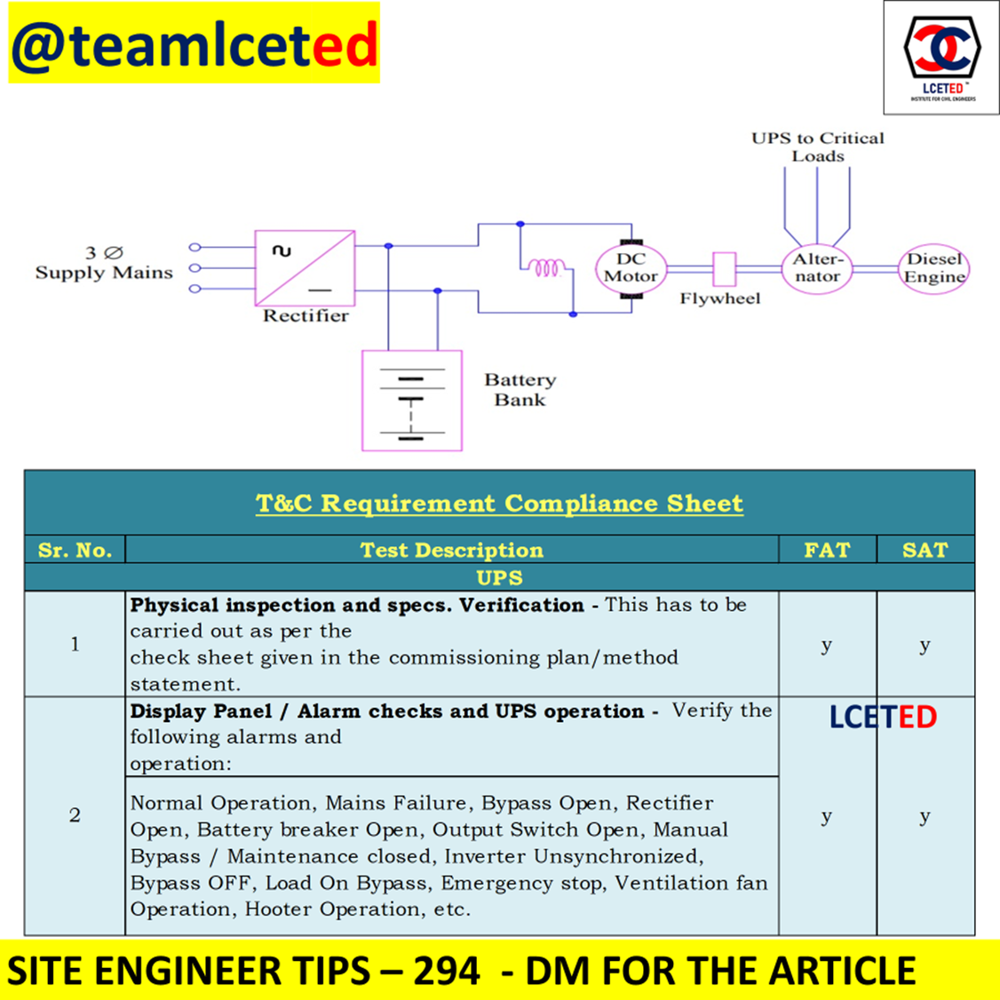
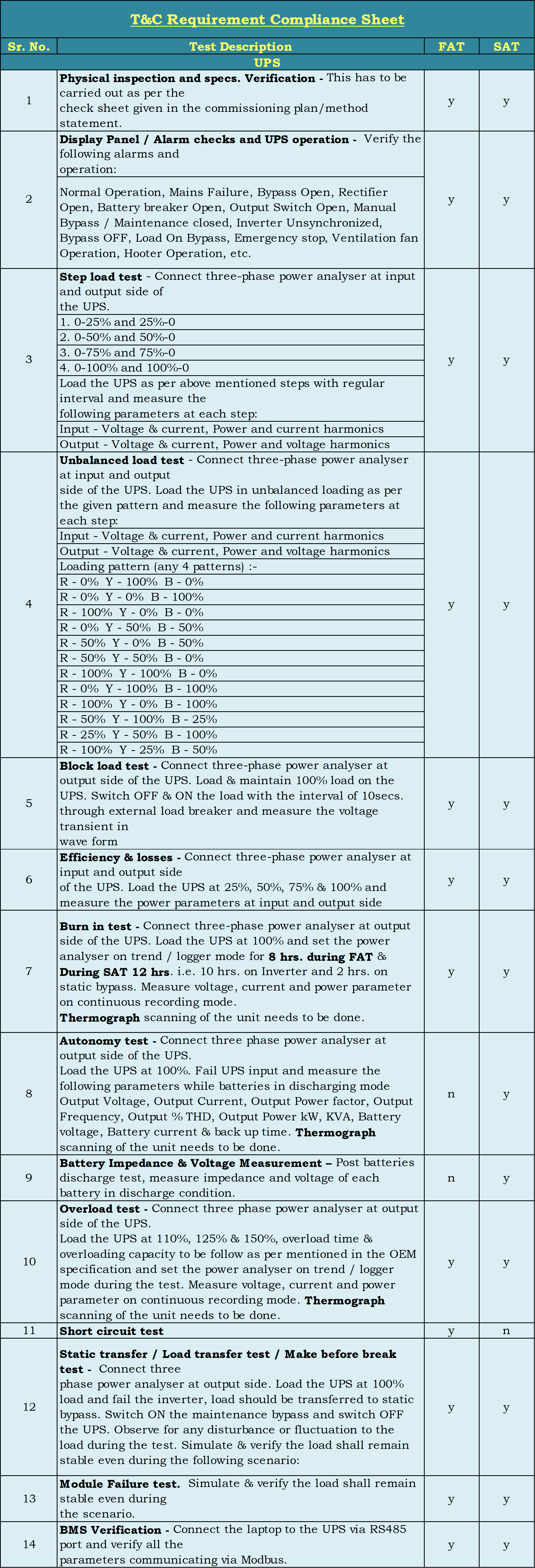
1. "Physical inspection and specs.
Verification - This has to be carried out as per the
check sheet given in the commissioning plan/method statement."
2. "Display Panel / Alarm checks
and UPS operation - Verify the following alarms and operation:"
"Normal Operation, Mains Failure, Bypass Open,
Rectifier Open, Battery breaker Open, Output Switch Open, Manual Bypass /
Maintenance closed, Inverter Unsynchronized, Bypass OFF, Load On Bypass,
Emergency stop, Ventilation fan Operation, Hooter Operation, etc."
3. "Step load test
- Connect three-phase power analyzer at input and output side of the UPS."
1. 0-25% and 25%-0
2. 0-50% and 50%-0
3. 0-75% and 75%-0
4. 0-100% and 100%-0
"Load the UPS as per above mentioned steps with
regular intervals and measure the following parameters at each step:"
Input - Voltage & Current, Power, and current
harmonics
Output - Voltage & Current, Power, and voltage
harmonics
4. "Unbalanced load test
- Connect the three-phase power analyzer at the input and output side of the UPS. Load
the UPS in unbalanced loading as per the given pattern and measure the
following parameters at each step:"
Input - Voltage & Current, Power, and current harmonics
Output - Voltage & Current, Power, and voltage
harmonics
Loading pattern (any 4 patterns): -
R - 0% Y - 100% B - 0%
R - 0% Y - 0% B - 100%
R - 100% Y - 0%
B - 0%
R - 0% Y - 50% B - 50%
R - 50% Y - 0%
B - 50%
R - 50% Y - 50% B - 0%
R - 100% Y - 100%
B - 0%
R - 0% Y -
100% B - 100%
R - 100% Y - 0% B - 100%
R - 50% Y - 100% B - 25%
R - 25% Y -
50% B - 100%
R - 100% Y -
25% B - 50%
5. "Block load test
- Connect the three-phase power analyzer at the output side of the UPS. Load &
maintain 100% load on the UPS. Switch OFF & ON the load with the interval
of 10secs. through external load breaker and measure the voltage transient in wave
form"
6. "Efficiency & losses
- Connect the three-phase power analyzer at the input and output side of the UPS. Load
the UPS at 25%, 50%, 75% & 100% and measure the power parameters at the input
and output sides"
7. "Burn in the test
- Connect the three-phase power analyzer at the output side of the UPS. Load the UPS at
100% and set the power analyzer on-trend / logger mode for 8 hrs. during FAT
& During SAT 12 hrs. i.e., 10 hrs. on Inverter and 2 hrs. on static bypass.
Measure voltage, current, and power parameters in the continuous recording mode.
Thermograph
scanning of the unit needs to be done."
8. "Autonomy test
- Connect the three-phase power analyzer at the output side of the UPS. Load the UPS at
100%. Fail UPS input and measure the following parameters while batteries in
discharging mode Output Voltage, Output Current, Output Power factor, Output
Frequency, Output % THD, Output Power kW, KVA, Battery voltage, Battery current
& backup time. Thermograph scanning of the unit needs to be done."
9. Battery Impedance & Voltage
Measurement – Post batteries discharge test,
measure the impedance and voltage of each battery in discharge condition.
10. "Overload test
- Connect the three-phase power analyzer at the output side of the UPS.
Load the UPS at 110%, 125% & 150%, overload time
& overloading capacity to be followed as per mentioned in the OEM
specification, and set the power analyzer on-trend / logger mode during the
test. Measure voltage, current and power parameters in the continuous recording
mode. thermograph scanning of the unit needs to be done."
11. Short circuit test
12. "Static transfer / Load
transfer test / Make before break test - Connect three
Phase power analyzer at the output side. Load the UPS at
100% load and fail the inverter, the load should be transferred to static bypass.
Switch ON the maintenance bypass and switch OFF the UPS. Observe for any
disturbance or fluctuation to the load during the test. Simulate & verify
the load shall remain stable even during the following scenario:"
13. "Module Failure test.
Simulate & verify the load shall remain stable even during the
scenario."
14. "BMS Verification
- Connect the laptop to the UPS via RS485 port and verify all the parameters
communicating via Modbus."
TYPES OF TESTING AND COMMISSIONING ON ISOLATION TRANSFORMER
1. "Physical inspection and specs.
Verification - This must be carried out as per the check
sheet given in the commissioning plan/method statement."
2. Display Panel / Alarm checks
operation
3. Measurement of winding resistance
(Primary & Secondary)
4. Insulation resistance test (Before
& after HI pot test)
5. Megger (Before & after HI pot
test)
6. HI pot Test - 2.5kV for 01min.
7. Vector group verification
8. Magnetic balance test
9. Voltage Ratio Test
10. Measurement of Short circuit
Impedance Voltage and Load Loss
11. Measurement of No-load loss
12. "Step load test
- Connect three-phase power analyzer at input and output side of the Isolation
Transformer."
1. 0-25% and 25%-0
2. 0-50% and 50%-0
3. 0-75% and 75%-0
4. 0-100% and 100%-0
"Load the Isolation Transformer as per above
mentioned steps with regular intervals and measure the following parameters at
each step:"
Input - Voltage &
Current, Power, and current harmonics
Output - Voltage &
Current, Power, and voltage harmonics
13. "Unbalanced load test
- Connect three-phase power analyzer at input and output side of the Iso Trx.
Load the Iso Trx. in unbalanced loading as per the given pattern and measure
the following parameters at each step:"
Input - Voltage & Current, Power, and current
harmonics
Output - Voltage & Current, Power and voltage
harmonics
Loading pattern (any 4 patterns):
R - 0% Y - 100% B - 0%
R - 0% Y - 0% B - 100%
R - 100% Y -
0% B - 0%
R - 0% Y - 50%
B - 50%
R - 50% Y - 0%
B - 50%
R - 50% Y - 50% B - 0%
R - 100% Y - 100% B - 0%
R - 0% Y -
100% B - 100%
R - 100% Y - 0%
B - 100%
R - 50% Y - 100% B - 25%
R - 25% Y - 50% B - 100%
R - 100% Y - 25% B - 50%
14. Inrush Current Measurement
15. Induced over-voltage Test
16. "Block load test @ 50% & 100%
load (Voltage transient to be observed at the output side)"
17. "Burn in the test
- Connect three-phase power analyzers at the output side of the isolation
transformer. Load the isolation transformer at 100% and set the power analyzer
on-trend / logger mode for 08 hrs. during FAT & 12 hrs. during SAT. Measure
voltage, current and power parameters in continuous recording mode. Thermograph scanning
of the unit needs to be done"
18. "Overload test
-Connect the three-phase power analyzer at an output side of the Iso Trx. Load the Iso
Trx. at 110%, 125% & 150%, overload time & overloading capacity to be followed as per mentioned in the OEM specification, and set the power analyzer on-trend/logger mode during the test. Measure voltage, current and power
parameters in the continuous recording mode. Thermograph scanning of the unit needs
to be done."
19. "BMS Verification
- Connect the laptop to the UPS via RS485 port and verify all the parameters
communicating via Modbus."
20. PDU Cubicle Panel
– Physical inspection, specs. Verification & Alarm Verification.
21. PDU Cubicle Panel –
Insulation Resistance & Torque Tightness verification
22. "PDU Cubicle Panel
– Primary injection test for TMD Breakers - During FAT this test is to be done on
the rated value of the breaker and during SAT this test is to be done on the set
values as per discrimination study."
23. PDU Cubicle Panel
- Secondary injection test for Micrologic breakers - During FAT this test is to be
done on the rated value of the breaker 160A & above rating and during SAT
this test is to be done on the set values as per discrimination study.
24. "Milli Volt Drop Test
– PDU Horizontal & Vertical joints to be verified using millivolt drop test
kit."
Test Instrumentation Required for FAT & SAT
1. 3-Phase Power Quality Analyzer (UPS) - 2 Nos.
2. 3-Phase Power Quality Analyzer (Iso. Trx.) - 2 Nos.
3. "External Load Bank (Up to 150% of UPS &
Iso. Trx. Rating)" - 2 Nos.
4. True RMS Multi-meter – 1 No.
5. True RMS Clamp meter - 1 No.
6. Insulation resistance tester - 1 No.
7. Phase sequence meter - 1 No.
8. Digital thermographic scanner - 1 No.
9. Torque Wrench - 1 No.
10. Battery Impedance Tester - 1 No.
11. Oscilloscope - 1 No.
12. Db Meter - 1 No.
13. Primary Injection Test Kit - 1 No.
14. Secondary Injection Test Kit - 1 No.
CLICK TO DOWNLOAD EXCEL SHEET


No comments:
Post a Comment